

LESSON 6 Chapter 5 Drag ANA Chapter 1
Chapter 5 Drag
X-15
First flew June 1959, last flight Oct 1968
354,200 feet Mach 6.7 (4520 mph)
31,275lbs takeoff 12,295 at landing
200mph landing speed
Launched from B-52
57,000lbs of thrust – anhydrous ammonia and lox
The outer skin was nickel chrome alloy called Inconel X
Used conventional controls in atmosphere used hydrogen peroxide thrusters for pitch, yaw and roll
Established benchmark hypersonic data
Stability, control, materials for high heat, shock interaction, hypersonic turbulent boundary layer, skin friction, aerodynamic heating, and heat transfer
Lift, a Brief Review
We know that lift is produced by low pressure above and high pressure below
We also know that lift is the force acting perpendicular to the relative wind
And that any increase in alpha will generate an increase in drag
Drag acts parallel to the flight path
In all steady state flight lift=weight and thrust=drag
–This is true in a descent
–Also true in a steady climb
However in initiating a climb an alpha change is needed to change the pitch
–Once airspeed stabilizes we are again in steady state
Any given alpha has a corresponding airspeed to achieve steady state
–As speed slows, alpha is increased to provide sufficient lift
–As altitude increases, a higher TAS is needed to provide sufficient lift
Remember that if the V is doubled it is at the square so lift goes up 4 times as much
Lift
There are 3 basic ways lift is generated on an airfoil:
–Bernoulli’s Principle
–Deflection (Newton)
–Downwash (Newton)
This is a bit of an over simplification of how lift is generated however
Lift generation, the real story
There are 3 concepts to lift generation
–Conservation of momentum
–Conservation of energy
–Conservation of mass
Newton’s laws explain the conservation of momentum
–Every action has an opposite and equal reaction
Bernoulli’s equation explains the conservation of energy
-Static pressure + Dynamic pressure = Total pressure
Euler equations explain the conservation of mass
–This is where it gets messy
Lift generation, the real story
The Euler equations are a series of calculus equations that relate 2 dimensions of velocity along x and y axis along with pressure and density
All equations must be solved simultaneously
This area of study is called Computational Fluid Dynamics
Engineers use this method to determine the conservation of mass airflow around the airfoil
Lift myths
Equal transit theory
Venturi flow
Skipping stone theory
Lift the Coanda Effect
The Coanda effect (pronounced cwanda)
This explains the air’s tendency to stick to a surface and bend around the curved portion of the upper surface
Newton’s law then takes over explaining the force generated by the bending of the air stream
As air flows over a curved surface, a negative pressure results which pulls the flow toward the airfoil’s surface
Drag defined
Drag is the component of the aerodynamic force that is parallel to the relative wind and retards the forward motion of the aircraft.
Drag
The Drag equation is: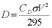
The coefficient of drag is the ratio of the drag pressure to the dynamic pressure.
Drag like lift is proportional to the dynamic pressure of the air and the area on which it acts.
The equation is much like the lift equation except that it measures the force in the stream-wise direction or parallel to the flow.
Drag
When talking about drag, there is a problem when determining the area to be used in the equation.
Drag is being generated by a three dimensional body but drag is only proportional to 2 dimensions of the body (length x width).
Use fuselage shape example Top, Side and Front.
Drag
As a standard most bluff bodies (fuselage, engine nacelles or landing gear use the projected frontal area or max cross section.
For wing or tail surfaces, the planform or top view is used.
Sometimes engineers will use the wetted area or the area that would get wet if the whole airplane were dunked in water.
Laminar Flow airfoils
When comparing an older 4 digit airfoil to one of the newer 6 series airfoils there is a noticeable decrease in drag coefficient called the drag bucket.
At low AOA the drag remains extremely low because the laminar flow remains laminar so far back.
At high AOA because of the sharper leading edge the CD goes up higher than the 4 digit airfoil.
Lift to Drag Ratio
The lift to drag ratio is a measure of efficiency.
A higher L/D is more desirable and the equation is:
The Curves
This particular curve relates the L/D ratio to α
L/D max is at the top of the curve
Notice the familiar Cl curve
And the Cd curve
L/Dmax
1. Highest point on the curve
2. The most efficient alpha
3. Min drag
4. Best glide
5. Max endurance (jet powered)
6. Max range (prop powered)
7. Max climb angle for Jets
Glide Ratio
Glide ratio is numerically equal to the L/D ratio
15/1 is both glide ratio and L/D ratio
Gross Weight does not effect glide performance.
Glide ratio is always the same
At a higher gross weight, V must be higher to achieve the L/Dmax α
What is the Glide Ratio for the B-19?
Induced Drag
Induced drag is drag generated by the production of lift or more accurately by the production of wingtip vortices.
The DI formula is:
or
Terms pg 65
Average chord – tapered wing take all chord lengths and average them
Aspect ratio = span (b)/chord (c)
high = glider wing
low = jet fighter wing
Induced Drag
Low pressure on top and high pressure underneath induces a vortex to form at each tip, causing a downward push on the air leaving the trailing edge.
This downward component known as downwash, causes the airstream to depart at an angle downward from the incoming air.
The lift vector being perpendicular to the flow, is now tilted backward at half the downwash angle.
Induced Drag
This means some lift is being generated opposite to the flight path this rearward component is by definition drag.
Induced drag is influenced by the CL and aspect ratio.
It increases directly as the square of CL and inversely as the aspect ratio.
Induced Drag
At low speed and low aspect ratio (short wings) induced drag is greatest.
Induced drag varies inversely with the velocity squared.
Ground effect
Ground effect usually happens when within one wingspan of the ground.
The surface actually helps destroy the downwash generated by the wingtip vortices and thus forces the lift vector more to the vertical thereby reducing drag.
Above 1 span length there is little or no ground effect
Ground effect
At 3/10 span length there is a reduction of 20% induced drag
For our planes that’s 9 feet up
At 1/10 span length there is a reduction of 50% induced drag
For our planes that’s 3 feet up
Ground effect
There is also a change in the effective angle of attack. Because of the altered downwash, an angle of attack increase is the result
Pitching moments develop downward for an aircraft entering ground effect because of the wings downwash not being able to help the tail generate lift downward.
Ground effect
Pitching moments develop upward for the aircraft leaving ground effect and may cause an increase in angle of attack such that the corresponding increase in drag may cause the aircraft to settle.
The pitch up and down moments are experienced entering and leaving ground effect
Level flight in ground effect results in a significant pitch up requiring a substantial force on the yoke to keep the nose down
There may be an increase in static pressure if the ports are below the wing. This will result in a decrease of airspeed the closer the plane gets to the ground or water.
Ground Effect Summary
On entering ground effect:
–Induced drag is decreased
–Nose-down pitching moments occur
–Airspeed may indicate slow
On leaving ground effect
–Induced drag is increased
–Nose-up pitching moments occur
–Airspeed may indicate higher
Parasite Drag
Parasite drag is the drag caused by protuberances and increases directly with the velocity squared.
The DP formula is:
Parasite Drag
Skin Friction – Drag caused by rivets, dirty surfaces, effects boundary layer
Form Drag – caused by the shape of the surface
Interference – collision of boundary layers of different surfaces
Leakage – pressure differences inside and outside the plane, like cracks in door seals
Profile – drag with regards to moving helicopter rotors
Definitions pg 72
Total drag
Total drag is the sum of induced drag and parasite drag
Drag Curves
The total drag curve has limitations
1. Parasite drag will be increased as stall alpha is reached because more frontal area is exposed
2. In high speed flight, wave drag may form as a result of compressibility.
The Total drag formula is:
Wing Loading
Power Loading